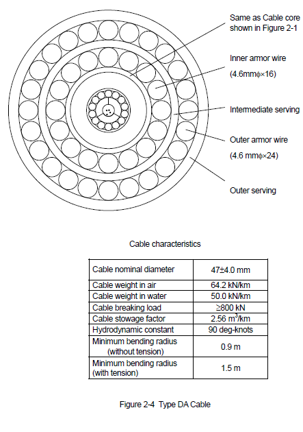
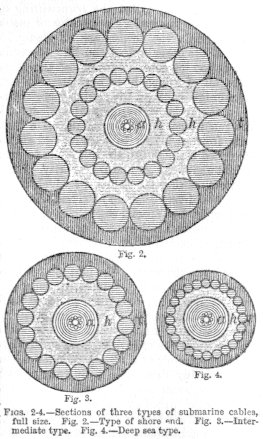
Subsea fibre optic cables come in many different sizes from 14mm diameter for Light Weight to 68mm+ for heavily armoured cables such as Rock Armour.
Armoured cables are used in shallow depths and in harsh areas of seabed terrain where abrasion or damage from fishing is likely to be caused.
A typical system will start with the shore end being in Double Armour for a kilometre or so before stepping down to Single armour and then Light Weight as the depth increases.
Cables are often buried using a plough towed behind the Lay Vessel during installation as every 1m of burial provides and increasing level of protection and is cheaper than continuing to make the cables from more and more armour which increases their cost and the difficulty to handle them.
Another side to cable weight is depth, the breaking strain of Double or Single Armour is approx 270kN. Laying a cable to a depth of 6Km+ would mean that the cable would have parted under its own weight before it reached the seabed.
To overcome this, Light Weight cables are used and can be installed to the deepest parts of the oceans - See Mariana Trench cable crossings.
Subsea cables are often damaged by anchors, fishing activity, earthquakes, subsea landslides, currents, typhoons and occasionally plant failure.
To span the long distances fibre optic cables need to have electrically driven Repeaters every 50km or so to boost the optical transmission and overcome optical dispersion which leads to frequency blurring and data loss.
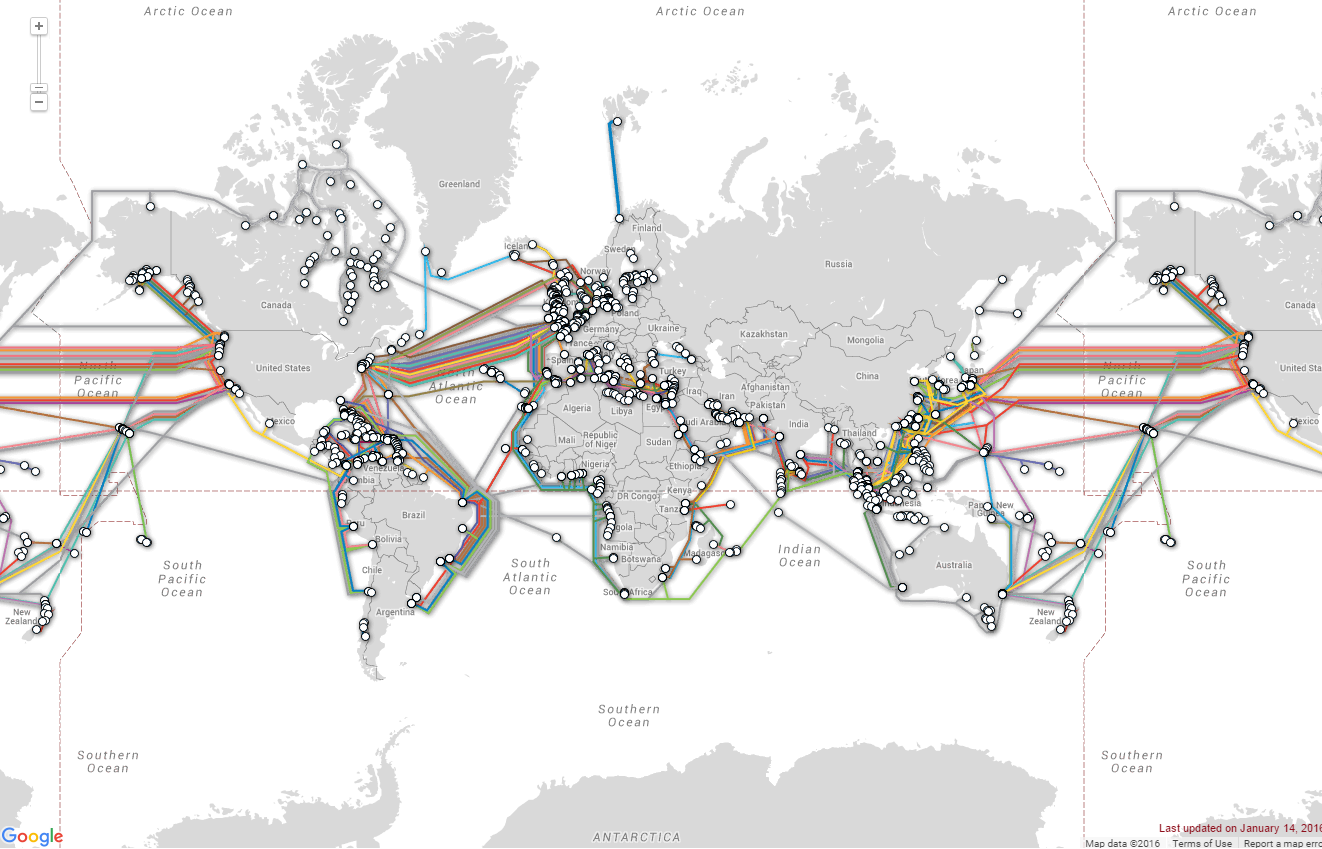
If a cable should go down the traffic is shunted to another operator’s cable or diverted through a different section of the cable. Many cable systems span the world and have multiple landing points or branches. This gives the ability to shunt traffic from a damaged section through a different landing station and onto a different operators cable or over the land network
To repair a subsea cable first the fault is located either using ohms law from the power feed equipment driving the repeaters if it is a short circuit or optically using an COTDR Optical Pulse Test Set if the fibres are broken or damaged.
Once the fault is located a repair ship is tasked for the repair. There are ships stationed all over the world covering different zones for cable repairs. The vessel will load spare cable into its tanks, often hundreds of Kilometres! Jointing kits and any replacement plant that is needed.
On arrival at the repair ground the vessel will either use an ROV if conditions permit to inspect and recover the cable end or will use a grappling rig to cut and recover the cable to the surface.
Once an end is onboard it will be tested clear for faults before being sealed and buoyed off to allow the ship to recover the other cable end and test to locate the fault. The vessel will then recover cable from the seabed to the fault and cut it out. It will then commence the initial joint where the stock cable end is joined to the system cable and laid back down to the seabed back towards the first end that way buoyed off.
On recovery of the first cable end the final joint is prepared, the stock cable is cut to length and the two ends joined to form the final bight.
Contrary to popular belief the cable doesn’t run through the entire length of the ship from end to end. Historically vessels such as the Pacific Guardian and the Atlantic Guardian are bow workers where the cable is deployed from the front of the ship clear of the props as the vessel moves backwards, they are also equipped to do long cable installations from the stern of the ship which gives rise to the misconception that cable is run from end to end.
Most modern cable ships are setup to use the large back deck as the cable operations deck, a final bight is essentially two cable ends up over the stern and joined together in a big loop inside the ship, this is then laid back to the seabed on ropes and a release hook.
The common construction of a subsea fibre optic cable working from the centre outwards is Fibres, Loose protection tube, Inner strand wires, Copper tube ( power path ) Polythene insulation, Armour wires, Nylon Serving.
The fibres are joined together using a fusion splicer that perfectly aligns the 7-20 micron sized fibres before fusing them together with an electric arc. A fusion splice is often much stronger than the parent glass of the fibre. The rest of the joint comprises of armouring and moulding the core of the joint in poly Xray testing and then assembling the rest of the case and armour ready for deployment to the seabed.
Ships such as the CS Cable Innovator can do entire Atlantic crossings without stopping where as other vessels such as CS Pacific Guardian and CS Cable Retriever are suited to repair work.
To sever all of the connections from a large country such as the UK, or America would be very difficult time consuming and ultimately fruitless as traffic can be shunted via other routes. The 2010 Earthquake in Japan severed nearly all of the cables on the Eastern Seaboard, breaking and burying a lot them. The country was still able to communicate via cables on the Western Seaboard whilst 9 cable ships were mobilised to repair the downed systems.
Some countries routinely cut cables on stealth operations against their rivals but this doesn’t allow them to listen in. It is not possible to cut into an optical cable and patch into it without being noticed and if you could you would not be able to decode and retransmit the data like on an old Coax Cable System.
Most cable operators use AIS Vessel tracking to identify ships that cross their cables and anchor near them so that they can seek restitution from the vessel owners.


