I think it is possible, assuming they have the following:
- a (stable) power source, a lemon battery will probably do just fine
- wires, or anything that can be used as such
- a way to solder on the memory chip inside the SSD
- a way to measure volts or at least detect if a digital signal is 1 or 0 (a led maybe?)
- a good knowledge of SSD internals and the SPI protocol
The thing is, you can't reasonably expect them to be able to use the SATA port without a microcontroler, but the data you want to read is stored inside chipchips that are much more generic.
Those memory chipchips are used inside all sort of devices, like cellphones, usb thumb drive, SD cards, embedded systems and so on.
They talk multiple protocols, some are fast and complex, some are really basic. One of those is the SPI protocol.
SPI requires basically 3 wires to work,: a clock, an input and an output. In SPI mode the microcontroller is the one that decide the communication speed with the clock signal.
In theory you can "bitbang" the clock and input signal making contact with a couple of wires, or 2 push buttons if you have them. To read the output you'll need a detector on the output line, it will detect one bit at a time. It can be a voltmeter, a led, or anything that can help you distinguish from 1 to 0.
The difficulty here is to solder on the tiny pin inside an SSD.
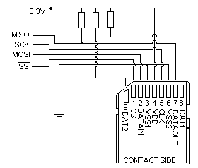
For the sake of completeness I have to point out that an SD card is much more compact and easy to work with. You don't have to solder and you can use much ticker wires. The wiring is the following:
SS is an enabler. It can be tied to ground and ignored for this answer.
Now, bitbanging the clock and the input by hand is tedious and error prone. A more advanced method may be to replace the 2 buttons / wire contacts with a perforated cardboard.
You take a strip of cardboard and trace 2 columns, one per sigal. On one column you drill an hole every even or odd row, it doesn't matter as long as you are consistent. This is your clock.
On the other column you drill an hole every time your input signal needs to be 1.
At this point you need to setup the contacts of the input and clock signal so that you can slide the cardboard between the contacts and have them open and close when the drillholes pass trought them.
This method will ensure 2 things:
- you can check your input on the cardboard before sending it
- you can send you input way faster and precisely, minimizing the mistakes.
Now, you have to write down the output signal on a piece of paper, every ones and zeroes, and start decoding it. It will take a long time, depending on the encoding, but that's it.
The data encoded on the card may be stored in a filesystem like FAT or EXT4, and that will require a very good knowledge of the filesystem structure, but they can also be stored in a raw format, for example plain ASCII codes starting from the first byte of the first block of memory. That will be much much easier to read.

